|
PRECISION: HOW TO ACHIEVE A LITTLE MORE OF IT, EVEN AFTER ASSEMBLY WILLIAM T. PLUMMER Polaroid Corporation, 38 Henry Street, Cambridge, MA 02139 USA ABSTRACT
INTRODUCTION Classical assembly methods used in manufacturing, manual or automated, are limited in the resulting precision they can offer. The traditional effort to improve precision by making tighter fits and closer tolerances may be an expensive and futile approach, and may even complicate the path to automation. Instead, we have found that better and less expensive results can be achieved by a fresh use of some old ideas from instrument design, together with emphasis on a conceptual plan when mechanical systems and their components are being designed. If it is true that some 80% of manufacturing problems are really design problems, then perhaps 80% of those design problems may be traced to a skimpy underlying concept of how all the necessary parts may be expected to come together to function with precision. Without a valid concept, the expensive drafting, machining, and assembly that follow may not lead to an acceptable conclusion.
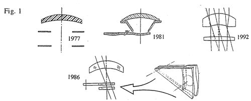
1. System Desensitized if Possible (Maybe from a Different Starting Point?) In multi-element photographic lenses, image aberrations are corrected by cancellation among three or more optical parts. This design form has the advantage that a camera can be adjusted in focus by a small motion of one optical part to cover a large range of subject distances. For full benefit the lens parts must be accurately spaced and centered in some kind of tube, without tilts. Image errors at the film arise quickly with construction errors. The manufactured lenses form a statistical distribution with a long tail of problem lenses, and the classic response has been to test and discard to meet a specification[1]. But by using a totally different design form as a starting point, the "landscape lens" of 1810, and upgrading it with aspheric surfaces and using a totally different concept for changing focus, we have developed a new family of photographic lenses in which all of the needed precision can be molded into the parts, leaving much larger tolerances for assembly. The first design in this series was the OneStep sold in 1977[2], and others followed as the Model 660 in 1981[3], the Spectra/Image in 1986[4], and the Vision/Joycam/Captiva in 1992[5]. (Fig. 1) The 1986 Spectra provides focus changes with a pair of symmetry-free aspheric optical surfaces.
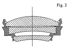
2. Arrangement of Components to Cancel Sensitive Errors Within a conventional lens structure, tilt problems can be countered by pairing lens elements with opposite effect and mounting them against each other, as in this fine-tuning corrector sub-assembly used in the Minolta Instant Pro, 1988. (Fig. 2) The first lens was positively retained against the second with a wire snap-ring seated on a ramped bore, holding between them a plastic shim washer chosen to correct system focus.
3. Avoidance of Abbe errors This classic problem is found when precision is established along a line that is parallel to but offset from the axis of interest, as when a measuring scale is placed on the far side of a print head driven by a lead screw. An example is found where numerous optical or mechanical devices are mounted above a solid plate, or mechanical "ground plane," and their upper extremities are expected to maintain the proper relationship. Sometimes electrical packages are installed just where their heat can best cause the plate to warp during warm-up. Well-placed diagonal braces can improve the results and actually save effort during the assembly.
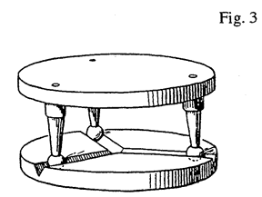
This classic consideration [6,7,8] is well known in the laboratory, but for some reason is under-used in product design. One can easily assemble hardware to unusually small tolerances without any tight clearances, as would be needed with fitted pins. We have used the form of three half-spheres seated in three radial vee-shaped grooves to mount an optical print head into a medical printer. (Fig. 3) This is an inexpensive and effective way to provide the necessary and sufficient six points of contact to support a rigid body with nearly perfect repeatability. Not only is the head easily replaced in a field service call, without loss of optical precision, but this design prevents the transmission of any distorting torque from the sub carriage into the optical assembly.
In a simpler form we have used three short tenons as supports for a lens in a camera shutter: if the lens is not parallel to the rest of the assembly, the error is unambiguous and can be measured and removed by adjustment of one or two of the tenon heights in a mold. This approach has been used very successfully to perfect each of three bumps supporting each of four plane mirrors in a many-component viewfinder manufactured in high volume. In the Polaroid SX-70 folding Single Lens Reflex camera a molded plastic aspheric concave mirror was spring-loaded against three bumps near its edge to place it accurately without any possibility of twist[9]. (The use of three fixed supports to locate a flat glass mirror would seem obvious, but in several products it was accepted only after four supports had warped or broken enough mirrors for everyone's satisfaction. My favorite example is an overhead projector design in which the upper mirror was glued to a sheet metal support held by screws at all four corners. A large fraction of the assembly labor was devoted to finding the right shim washers to remove the twist from the mirror and achieve the optical specification, a task better abolished by design than automated.) The lead screw is a familiar device often mounted improperly with a tightly constrained moving nut, where lateral freedom should be provided, perhaps with a flexure coupling, for both easier assembly and better performance. Both over constraint and under constraint can be avoided or controlled through kinematic mounting principles.
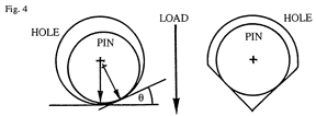
In a common device such as a sheet metal linkage attached with round holes fitted with round rivets, or ending on a round pin, the loose elements will lead to errors even under tension or compression, because of the ability of the parts to perch on a local slope, limited only by the coefficient of friction, and small changes in direction of the contact forces will move it. (Fig. 4) A round pin of radius a seated in a round hole of radius b can be mislocated by up to (b-a)(1-Cos q) in the load direction, where Tan q = m is the coefficient of friction. Properly oriented vee-shaped holes will remove this error without requiring tight fits, and any moving hinge-like member will seat more accurately in a vee-block than in a round bore. Similarly, a square pin may provide better positioning for a part pivoted about it.
6. Compliant Restraints True kinematic or deterministic seating requires a restraint to maintain contact without damaging the components with Hertzian forces or deforming their shape. Springs, snaps, and other measures used for this should be designed for the appropriate force. The resultant elastic rate for part location accuracy is not limited by the restraining spring until the part is grossly unseated.
The movable component must seat reliably. A spring force should be applied with its line of action somewhere within the perimeter of the support. An automated assembly device may have to detect variances in spring strength or part shapes that will cause problems.
Non-camming surfaces should be provided for spring pressure against moving parts to achieve positive location under all conditions. Fine screw adjustments made against a movable part of an assembly should be in contact with a surface oriented to remove camming under natural motion or residual looseness.
Precision Inspectors prefer idealized tools, such as perfectly round pins, for their work. If a hinge pin is designed with a flat to avoid molding or plating flash on the mating part, the gauge must have the same design. I have seen molded parts cut open for measuring to avoid making non-standard gauge pins!
Molded cantilevered snaps are convenient fastening devices for high-volume products. All snaps are designed with some kind of tapered lead-in shape to cam them open for assembly, but not all are designed with an equally important ramped surface on the underside to assure firm contact with the part held, perhaps to position that part kinematically or, as in an electronic flash assembly, to seat a reflective foil solidly against its housing.
Remember to design springs! Automated product design cycles now largely bypass the Model Shop, where people used to get these things right before manufacture. This includes the dimensions on molded snaps and such issues as the sag of some assemblies under their own weight.
A classic tool in precision mechanical design is to imagine all parts to be made of rubber[7,10]. This tool also works in designing for manufacture.
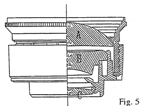
In one high-volume plastic triplet lens design the middle "B" element, with extreme sensitivity to tilt or centering errors, was mounted to fit its plastic housing like a cork in a bottle, with an extended flange to level it when fully seated. (Fig. 5) With perfect parts the errors were small. But in real life the fit was either too tight, leading to perfect centering but poor tilt, or too loose, giving perfect tilt but poor centering. A better concept here would be an elastic centering fit within the thin tubular part of the mount, with a series of symmetric and parallel straight ridges spaced around the edge of the lens. The ridges would interfere a little with the fit into the tube, deform the tube slightly toward a polygon, and achieve centering by elastic averaging. The lens would always seat fully and level perfectly. In another application of elastic averaging a circular plastic spline has been used in a mounting interface between flanges to keep axial assemblies of different materials accurately centered on each other over a large temperature range.
14. Use of Glue as a Cast-in Spline In the previous example, the circular plastic spline was cast in place so that some adjustment in centering was possible before curing. In another product, glue injected in facing lathe-cut grooves was used to attach two tubular parts of a brass lens cell without depending on adhesion to the chemically blackened surfaces.
If you use snap fasteners, balance them for force. In one camera lens assembly, a glass-plastic subassembly gave trouble when not tightly staked together because the combination was not symmetrically held. In a previous camera a square lens mount was seated on a ring machined surface of a casting and bolted into place at its four corners. The corners were not directly supported, and with fine screws even moderate torque produces high tensions. All was well with four screws, or two, but three screws caused large optical problems because of unbalanced distortion of the lens assembly.
If the compound linkage will be under compression in the product, donít test it under tension. If the ends will mate with loosely fitted pins, gauge the assembly that way and not with spring-loaded conical points. If something is going to sag under its own weight, test it right side up. If carefully done, functional testing of a complex part or subassembly may reduce all of the tolerance errors to one or two resultant "errors" that can be corrected where most convenient.
The repeatability of most high-volume manufacturing processes will justify much better component precision than the makers will promise on the first pass. The resultant errors found in functional gauging can most easily be compensated out if, in the program plan, a schedule is provided for doing so, and if certain parts of a large mold or punch are bolted in for easy shimming or replacement. The adjustment may be as simple as resetting a pin in a hole to change a tenon length, or rotation of a pin with an eccentric hole to move a molded tenon laterally. Tool adjustment will normally be resisted, but it may be the fastest and least expensive way to achieve system precision.
Watch for friction changes in marginal designs as the result of oxidation, grease migration, and the like. One molded plastic part filled with a high ratio of chopped glass fiber gave trouble when molded at a cooler cycle by a new vendor: the surface was covered by little glass bristles that gave friction problems with a moving part. The problem had not been seen before, and the print did not mention it.
Instead of building a micrometer into every assembly for final adjustment, use loose parts, use an external micrometer in the assembly fixture, and then inject glue to hold everything in place. Or hold a subassembly in a functional fixture, locate a component such as a plane mirror exactly where it is supposed to be relative to that first fixture, and inject a UV-cured elastomer where appropriate to attach the component with all foregoing tolerances compensated. I have seen exactly this procedure used to cast concrete headers across sets of four pilings in the course of building a causeway across marshy ground.
In building an expensive 35 mm camera, one of the last mechanical operations after most of the assembly is complete is to machine the final face on the rails that position the negative at the film gate, to remove all of the tolerance accumulation from the lens seat. This "closed loop" process is superior to the "open loop" alternative of trying to make all of the parts better until the assembly works. Final system adjustments may require more technical attention toward the end, but can save cost by opening tolerances at all previous stages. In another example, adjustments are all easy if made in a particular sequence: First one positions a laser diode to center on an initial lens, then one seals the adjustment and positions the subassembly, with a highly magnified image, where it will meet the rest of the system. The first adjustment cannot then be repeated because the high magnification makes it too touchy, and in one case we deliberately designed the parts to restrict later access.
To achieve precision in assembly, one must look for it or test for it with suitable equipment at key stages, or at the end. Responsibility for "assembly" may be interpreted as assurance only that all the parts are present and solidly attached, not necessarily that the design concept has been fully represented in the hardware. Discussions around these issues may reveal areas of design where assumptions have not been communicated fully to the factory, and manufacturing issues that have not been communicated fully to designers. Even if it is never to be built, a "global functional tester" should be invented and discussed by design and manufacturing groups in a mutual effort to discover where problems could be hidden.
1. W.T.Plummer, "Fast Automatic Lens Testing of Extended-Field Image Quality," Appl. Optics 15(3),805-810(1976).
Paper presented at the FIFTH INTERNATIONAL SYMPOSIUM ON ROBOTICS AND MANUFACTURING, Maui, Hawaii, August, 1994.
|
