| IPES-8 (15-19 May 1995)
PRECISION ENGINEERING AT POLAROID W. T. Plummer, J. J. Mader, J. W. Roblee, and J. Van Tassell Optical Engineering Department, Polaroid Corporation 38 Henry Street, Cambridge, MA 02139, USA
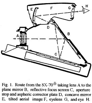
The industrial use of Precision Engineering concepts in machines designed, built, and operated at Polaroid has given us a unique freedom in optical design. By using machined and molded optical surfaces with non-rotational geometry we have provided new kinds of product function, higher image quality, and advantages in size, weight, and cost. The first of four ultra-precision machines in this series has been used for profile measurement only, and was completed in 1968 [1]. It is built of granite, uses aerostatic linear slides and laser interferometry for position control, and is driven by linear electric motors. For vibration protection it is supported on self-leveling pneumatic isolators. Measurements are normally made at uniform velocity with a constant-force contact probe, tipped with a 0.8 mm ruby ball, over a 100 mm path, with a 25 mm measurement range. The original resolution was about 0.08 micron, but was later upgraded to 0.01 micron. The force transducer at the probe is a capacitance gage coupled to the tip through a bell crank lever with a flexural hinge. The dead weight of the measuring probe and its slide is supported by an overhead flotation tank. A third axis is provided by a precision screw, for accurate centering and for lateral translation so that surfaces can be mapped. In 1969 our first procedure required accurate placement of the work to be measured, so that discrepancies from design could be plotted to a large scale on chart paper. We quickly replaced this with punched tape and a time-shared computer terminal, so that the computer could search for the best fit. Opticians were able to work quickly and naturally from expanded graphs of the measured errors to correct optical surfaces to any degree required. We progressed to a self-contained automatic calculator and later to a small computer. After two later changes in the interferometers and control systems this machine is still in use -- now in a factory environment -- for daily measurements of tools and molded lenses. Our second ultra-precision machine, completed in 1973, is configured as a lathe, with two stacked aerostatic slides and no tailstock, and is used almost constantly for generating surfaces with rotational symmetry. This machine is also built principally of granite, but uses slide components made of cast and lapped soft aluminum. (The aluminum is impregnated with a polymer to fill its porosity, is anodized for surface hardness after lapping, and is re-lapped if necessary.) We used a similar but larger design of linear electric motor, similar but larger pneumatic isolators, and similar laser interferometry with 0.01 micron resolution, to be upgraded soon to 0.005 micron. We have 15 cm axial and radial travel, and 15 cm height adjustment of the tool post. Work is held by a Professional Instruments "Blockhead" air bearing spindle. We originally built this machine to make tools for a molded concave mirror in the viewfinder of our SX-70® camera, described by an eighth-order polynomial asphere of revolution [2]. (Fig. 1.) In 1977 we used it to tool the first aspheric picture-taking lenses ever used in high-volume cameras [3]. Because we have found craftsmanship still important to both excellence and efficiency, all of this work is carried out by an experienced optician, who is sensitive to the quality of the surface as it is produced and can make sound decisions.
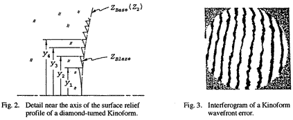
Although we had built this second machine for generating aspheric metal mold components by grinding stainless steel with an abrasive wheel, we quickly found that we could also directly cut optical surfaces with a diamond tool bit [4]. We have made a variety of prototype optical parts in plastics, aluminum, brass, germanium, and other non-ferrous materials. The machine is solid enough to cut such surfaces to an excellent finish even with a pointed diamond, rather than a curved edge or a blade, so we also have been able to form Fresnel surfaces of both lens and mirror quality with properly curved facets. Such surfaces can be cut up to 30 cm diameter. We have used this capability to cut "kinoform" optical surfaces directly, making a part that is at the same time a Fresnel (echelon) lens and a Fresnel zone plate [5]. All of the cut grooves in a kinoform have about the same depth; for a transmitting kinoform that depth is about 1/(n-1) wavelength of the light used, where n is the refractive index. (Fig. 2.) For a reflecting kinoform the depth is half the wavelength to be used, and in both cases the irregularity tolerance is small compared with the feature size. Our first samples had 1215 grooves and were cut in early 1989, and we have published a full-aperture interferogram to show that all of the facets combine coherently for a continuous wavefront [6]. (Fig. 3.)
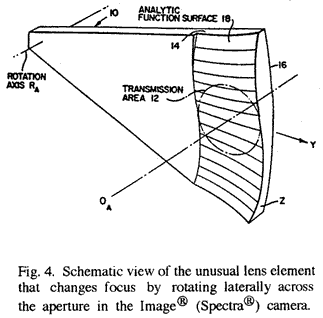
Unlike the "binary optics" equivalent, the diamond-cut kinoform can be made with high diffraction efficiency at high numerical aperture, and our test samples were effective as an unassisted f/2 lens, with a facet width of 2.6 microns at the edge. Because such kinoforms can also be cut on curved and aspheric surfaces, we have designed and made lenses based on them that can be athermalized (in one optical element) for constant back focal length, for corrected and constant spherical aberration of all orders, and even for corrected and constant coma [7,8]. We built the second machine with a removable measuring head so that work could be profiled in place. That provision was unnecessary, as the work can easily be removed and measured on another machine without loss of precision; the important information, the true zero of the radial coordinate and the exact size of the cutting tool, are independent of any replacement error. A removal, measuring, and replacement cycle takes less than 30 minutes. Our third ultra-precision machine was designed for three-axis profilometry, with active interferometric control in X, Y, and Z axes, and was completed in 1983. We copied the constant-force probe from our first machine and the heavier linear motors from the second, and gave the third machine a controlled working volume of 30 cm x 15 cm x 15 cm. One axis motion can be manually doubled from 15 to 30 cm with a lead screw. We again used stacked air slides for lateral motions and overhead flotation to support the weight of the probe and its slide. This machine has been used routinely for measuring the quality of optical surfaces of all kinds, including some with no rotational symmetry. Our resolution is again about 0.01 micron, and system noise is normally within 0.03 microns. Control and computation are provided by a networked minicomputer. For non-symmetric shapes the output data display is an isometric graphic of the error found, combined with a topographic map and some summary numbers. At times this machine has also been used for ruling or fly-cutting precise linear structures, and we have used it for measuring and qualifying the roundness of diamond tools. Customized software and control features have made the machine easy and efficient to use. The first two non-rotational aspheric optical surfaces used in high-volume products by Polaroid were molded on viewfinder lenses in the SX-70® cameras (and their later evolved models) manufactured from 1973 to 1986, and made possible the unique folding single-lens-reflex viewing system [9,10]. We cut the tools by using commercial numerical-control grinding equipment just past the limit of its capability. Two more non-rotational aspheric optical surfaces were used in 1986 in a compact and effective focus system for the picture-taking lens of the Polaroid Image® (Spectra®) camera. In this design, two lenses did not even have mirror symmetry: each required an eighth-order polynomial with 44 coefficients for its definition [11]. By rotating crosswise over the lens aperture (Fig. 4), one of these parts changes the camera focus automatically from infinity to 0.6 m, and the second cancels undesired coma produced by the first.
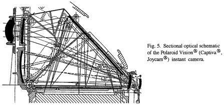
We used another pair of non-rotational aspheric optical elements in the single-lens-reflex viewing system of our Vision® (or Captiva®, or Joycam®) camera in 1992 [12]; this time one of them was used as a concave mirror, and was held to respectively tighter tolerances. (Fig. 5.)
Our fourth ultra-precision machine was designed for arbitrary Cartesian three-axis grinding of mold components -- to improve upon equipment commercially available -- and we can use it to make an optical surface of almost any form that can be described mathematically. We again used stacked aluminum air slides, but for better access provided flotation support for the vertical axis from below. The controlled working volume is 30 cm x 15 cm x 15 cm. Since completing the machine in 1994, we have routinely achieved non-symmetric optical surfaces with a ground RMS accuracy of 0.1 micron or better, and a finish that can be polished quickly without loss of figure. In both accuracy and finish we have improved upon our previous (commercial) capability by better than a factor of ten.
References:
|
